
www.magazine-industry-usa.com
03
'26
Written on Modified on
Siemens Expands Capital Software with 3D Electrical Design Capabilities
The added features permit electrical and mechanical engineers to work concurrently within a shared 3D context, facilitating interdisciplinary collaboration and decreasing late-stage design modifications.
www.siemens.com
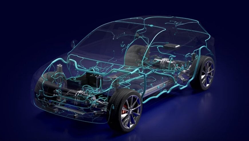
Siemens has introduced new 3D electrical design capabilities within its Capital software to combine wiring design and physical harness routing into a single, model-based workflow that spans the Siemens Xcelerator portfolio of industry software.
Addressing Workflows in Electromechanical Engineering
As electrical systems and software content expand in complexity, disconnected electrical computer-aided design (ECAD) and mechanical computer-aided design (MCAD) workflows frequently cause project delays, manual data handoffs, and expensive product rework. Siemens resolves these system discrepancies by integrating Capital within Designcenter software for advanced product engineering and Teamcenter software for product lifecycle management (PLM).
This technical framework allows engineering teams to design, validate, and manage electrical systems directly inside the native mechanical design environment. Frances Evans, senior vice president of Lifecycle Collaboration Software at Siemens Digital Industries Software, noted that the update allows manufacturers to pair electrical system design, including artificial intelligence (AI) driven harness development, with 3D mechanical design in a unified, model-based workflow without compromise. This model-based configuration is intended to lower development risk while boosting innovation through cross-discipline visibility, early identification of design errors, and structured decision-making for complex electromechanical assemblies.
Data Continuity and System Validation
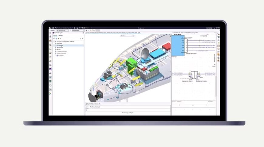
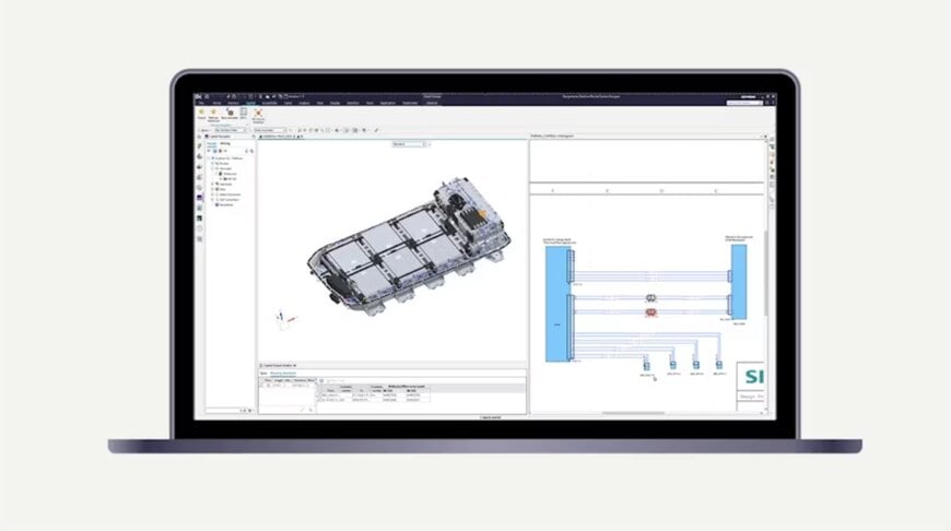
The new 3D electrical design architecture supports early validation of electrical layouts, improves data continuity across the enterprise digital thread, and eliminates manual handoffs between distinct engineering divisions. By visualizing electrical components and wiring geometry directly in 3D, engineers can identify physical routing conflicts earlier and align the initial electrical design intent with final mechanical implementation.
Chad Jackson, CEO and chief analyst of Lifecycle Insights, stated that cross-disciplinary conflicts between electrical and mechanical teams are relatively inexpensive to resolve early but become increasingly difficult to rectify late in the cycle once adjacent subsystems harden around them. Jackson added that a shared 3D context connecting electrical and mechanical engineers from the start of harness design renders early-stage problem resolution operationally possible rather than remaining a theoretical process aspiration.
The primary operational advantages of the integrated system include accelerated product development via early electrical system validation, enhanced ECAD-MCAD interaction in a single 3D workspace, and reduced overall costs and project risks through minimized downstream rework. Furthermore, engineering productivity is supported by utilizing familiar electrical and mechanical design tools supplemented by AI-driven automation.
Additional Context
This section details technical specifications not included in the original news release.
The convergence of ECAD and MCAD environments relies on standardized data exchange protocols to maintain data schema integrity across different software tools. Historically, electromechanical engineering teams utilized traditional file formats such as DXF, STEP, or IGES to transfer structural outlines. However, these formats lack the necessary electrical intelligence, including netlists, terminal crimp data, signal separation rules, and wire cross-sectional areas.
Modern collaborative electromechanical platforms utilize specialized data exchange schemas like IDX (Incremental Design Exchange, based on ProSTEP iViP profile) or the automotive KBL (Kabelbaumliste) standard. These protocols enable true bidirectional incremental data exchange. Instead of re-importing a complete harness assembly dataset, the system synchronizes only the delta changes—such as moving an electrical connector component or modifying a wire bundle diameter—retaining localized attributes and preventing data overwrite errors.
In AI-driven wire harness development, machine learning algorithms automate repetitive, rule-based engineering tasks. Wire harness routing algorithms calculate the mathematically shortest path or optimized multi-criteria path through complex 3D mechanical geometries while adhering to defined electrical and safety constraints.
Furthermore, automated part selection routines query localized database repositories to automatically match compatible terminals, wire seals, cavity plugs, and heat-shrink sleeves to specific connector housings based on wire gauge specifications. This rule-based automation transforms logical schematics into fully embellished, manufacturing-ready formboard drawings and accurate bills of materials (BOM), optimizing physical material utilization and manufacturing line balancing.
Edited by Romila DSilva, Induportals Editor, with AI assistance.
www.siemens.com
